

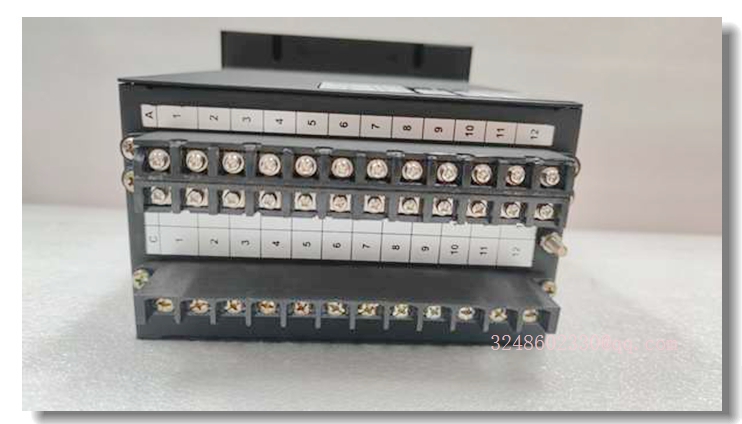
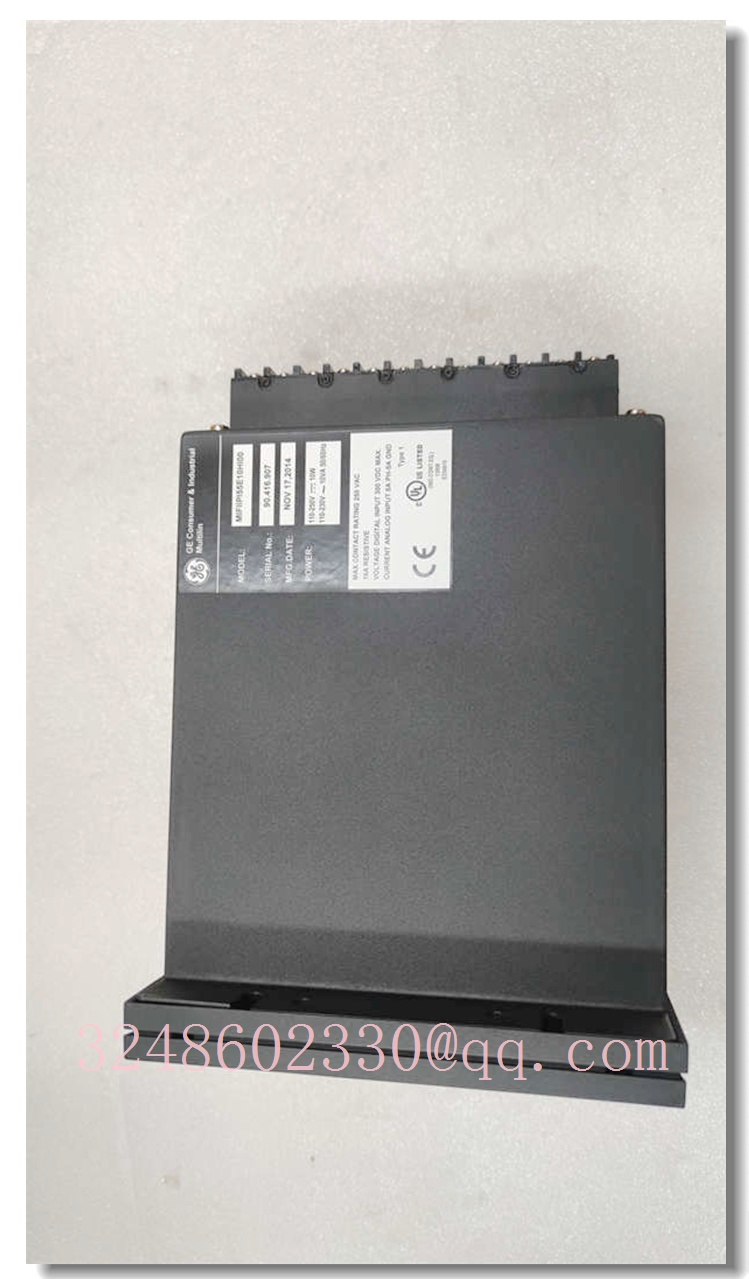
MIFII PA55E10H100 | High-Precision Industrial Control Module
Meta Description
The MIFII PA55E10H100 is a high-performance industrial control module designed for precision signal processing in harsh environments. Offering robust isolation and reliable operation, it is ideal for complex automation systems.
Product Core Synopsis
The MIFII PA55E10H100 is an advanced industrial control component engineered to bridge the gap between high-level control systems and field devices. Designed for precision and durability, this module facilitates accurate signal transmission and processing, ensuring that automated processes run smoothly and efficiently. Its architecture typically focuses on high stability and resistance to electrical interference, making it a preferred choice for critical control loops in manufacturing and processing plants.
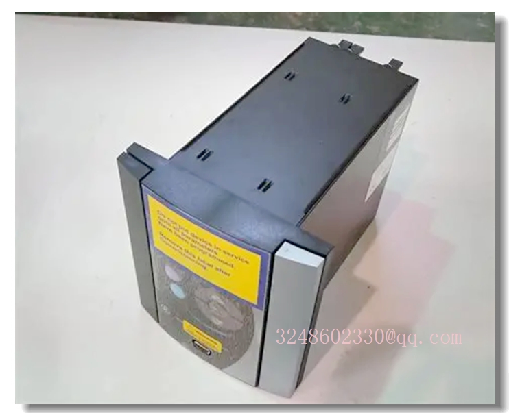
MIFII PA55E10H100
Main Technical Specifications
| Specification | Details |
|---|---|
| Model Number | PA55E10H100 |
| Brand | MIFII |
| Product Type | Industrial Control Module / Interface Module |
| Input Signal | Compatible with standard industrial voltage/current signals (e.g., 0-10V, 4-20mA) — *Verify specific input requirements* |
| Output Signal | High-precision analog output or relay driving capability — *Verify specific output requirements* |
| Supply Voltage | 24 V DC (Standard industrial range) |
| Isolation | Channel-to-channel and channel-to-bus isolation (typically 500V — 1500V) |
| Operating Temperature | -20°C to +60°C |
| Storage Temperature | -40°C to +85°C |
| Humidity | 5% to 95% (non-condensing) |
| Protection Rating | IP20 (for cabinet installation) |
| Mounting | DIN rail mounting |
| Termination | Screw terminal blocks or pluggable connectors |
Quality Control Procedures
To ensure the highest reliability and performance, the MIFII PA55E10H100 undergoes a rigorous quality assurance process:
- Incoming Material Inspection (IQC): All raw PCBs, electronic components, and connectors are inspected for authenticity and physical defects upon arrival at the facility.
- In-Process Quality Control (IPQC): During assembly, automated optical inspection (AOI) systems verify correct component placement and soldering integrity.
- Functional Testing: Each unit undergoes a comprehensive “burn-in” test and functional calibration under load to ensure it meets all voltage, current, and timing specifications.
- Final Quality Control (FQC): A final visual and diagnostic inspection is performed to check for cosmetic defects and firmware versioning.
- Safety and Compliance: Modules are tested for isolation resistance, dielectric strength, and compliance with CE and RoHS standards.
Recommended Related Models (Brand: MIFII)
- MIFII PA55E05H050: A lower capacity version of the interface module, suitable for smaller control cabinets with reduced I/O density requirements.
- MIFII PA55E20H200: A high-density variant capable of handling higher signal loads or a larger number of channels for complex systems.
- MIFII PC50X Series: A series of communication processor modules designed to work alongside the PA55 series for network integration.
- MIFII PS40U: A dedicated industrial power supply unit recommended to provide stable power to the PA55E10H100 and associated modules.
- MIFII TB50-R: A matching DIN rail terminal block designed for secure and easy wiring of the module.
- MIFII CP75-K: A coprocessor module used for advanced logic execution in conjunction with the base I/O modules.
Frequently Asked Questions (FAQ)
Q1: Is the MIFII PA55E10H100 compatible with standard PLC systems?
A: Yes, the module is designed with standard industrial signal levels in mind, making it compatible with most major PLC brands (such as Siemens, Allen-Bradley, and ABB) when correctly configured.
Q2: What is the typical lead time for a replacement unit?
A: Lead times can vary depending on stock availability. However, due to its standardized design, it is often readily available or can be shipped within 5-7 business days.
Q3: Does this module support hot-swapping?
A: Generally, this module requires a power-down for installation to prevent electrical surges or data corruption unless the host rack specifically supports hot-swap functionality.
Q4: How do I reset the module to factory settings?
A: A factory reset can typically be performed by holding down the configuration button (if available) during power-up or by initiating a reset command via the configuration software.
Q5: What is the warranty period for this product?
A: The standard warranty period is typically one year from the date of purchase, covering manufacturing defects and failures under normal operating conditions.
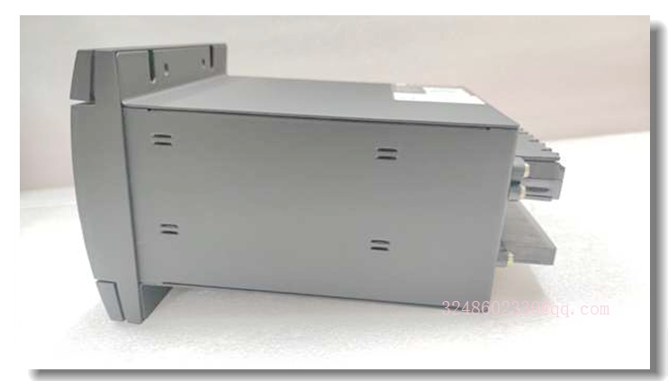
MIFII PA55E10H100
Installation and Configuration Guide
1. Safety Precautions
- Ensure that the power supply to the DIN rail or cabinet is completely disconnected before installation.
- Verify that the environmental conditions (temperature, humidity) within the cabinet meet the module’s specifications.
2. Mechanical Installation
- Mount the module onto a standard 35mm DIN rail.
- Secure the module by snapping it into place or using the provided locking clips to prevent vibration loosening.
3. Wiring
- Connect the power supply leads (24V DC and GND) to the designated power terminals.
- Connect the input signal wires from your controller or sensors to the input terminals.
- Connect the output wires to your field devices (actuators, valves, etc.) to the output terminals.
- Ensure all screws are tightened to the recommended torque to prevent loose connections.
4. Configuration
- Power up the system.
- Use the manufacturer’s configuration software (via USB or Ethernet port, if available) to set the input ranges, output ranges, and filter settings.
- If no software is available, check for DIP switches on the side of the module to manually set the operating mode.
- Once configured, monitor the status LEDs to verify normal operation.
5. Testing
- Apply a known test signal to the inputs and verify that the output response is within the expected range.