

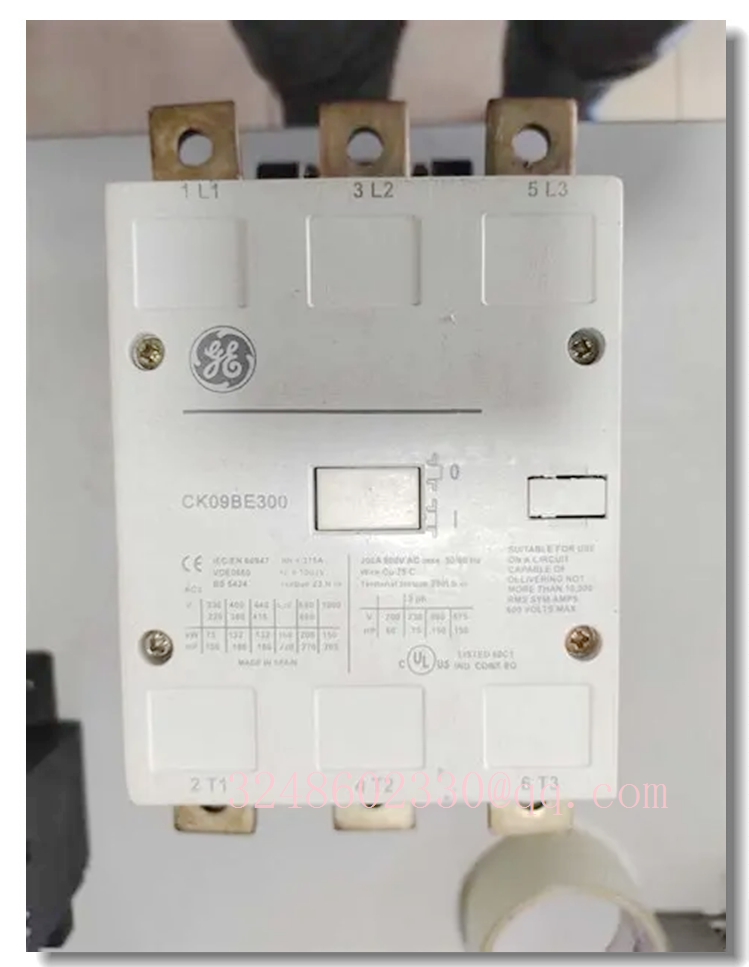
GE CK Series Contactor CK09BE300 — AC/DC Coil Control Contactor for Industrial Motor and Power Switching Applications
Meta Description
GE CK Series CK09BE300 contactor for motor control, power distribution and automation panels. Designed with AC/DC electronic coil control, auxiliary contact options and IEC/UL-compatible ratings. Verify exact coil voltage, pole configuration and auxiliary contact code before ordering.
Product Overview
The CK09BE300 is positioned within the GE CK series of industrial contactors, commonly used in motor control centers, machine control panels, HVAC systems, pump stations and general power switching applications. CK series contactors are designed for reliable operation under frequent switching conditions and are suitable for both AC and DC control circuits when equipped with an electronic coil module.
The “CK09” frame typically indicates a medium-duty contactor size, while the “BE” designation generally refers to a contactor with an electronic coil control circuit. The final digits usually define auxiliary contact configuration and coil voltage, so CK09BE300 should be confirmed against the original nameplate or purchase documentation.
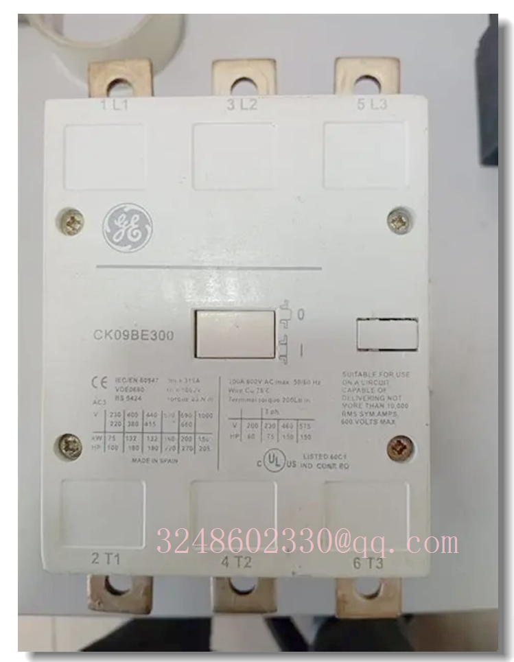
CK09BE300
Key Technical Specifications
For reference, similar CK09BE models such as CK09BE411 are rated around 400 A AC-1 and 250 A AC-3 at 380/400 V, with approximately 132 kW motor power at 400 V. CK09BE300 may have a different auxiliary contact or coil configuration, so these figures should not be treated as confirmed ratings.
Quality Control Procedures
- Incoming inspection: Verification of part number, coil voltage, pole configuration and auxiliary contact code.
- Visual inspection: Check housing, terminals, arc chutes, labels and mounting hardware for damage.
- Electrical testing: Coil resistance, insulation resistance, contact resistance and dielectric strength tests.
- Functional testing: Make/break operation, auxiliary contact sequencing and mechanical interlock checks.
- Endurance verification: Mechanical and electrical life testing according to applicable IEC/UL requirements.
- Final documentation: Batch traceability, test records and conformity certificates where available.
Related CK Series Models
- CK09BE411D — 24 V coil, 1 NO + 1 NC auxiliary contact
- CK09BE411J — 110 V coil, 1 NO + 1 NC auxiliary contact
- CK09BE411N — 220 V coil, 1 NO + 1 NC auxiliary contact
- CK09BE411U — 380 V coil, 1 NO + 1 NC auxiliary contact
- CK08BE411N — Smaller frame, 220 V coil option
- CK10CE411N — Higher frame size, 220 V coil option
Frequently Asked Questions
What is the CK09BE300?
It is a GE CK series industrial contactor model. The exact coil voltage and auxiliary contact arrangement should be confirmed from the nameplate or order data.
It is a GE CK series industrial contactor model. The exact coil voltage and auxiliary contact arrangement should be confirmed from the nameplate or order data.
Can CK09BE300 be used for motor control?
Yes, CK series contactors are commonly used for AC-3 motor switching. The exact motor rating must be confirmed from the product label.
Yes, CK series contactors are commonly used for AC-3 motor switching. The exact motor rating must be confirmed from the product label.
Does it support AC and DC control circuits?
CK series contactors with an electronic coil module can support AC/DC control circuits, but the allowable coil voltage range must be verified.
CK series contactors with an electronic coil module can support AC/DC control circuits, but the allowable coil voltage range must be verified.
Is CK09BE300 the same as CK09BE411?
Not necessarily. The suffix usually defines auxiliary contacts and coil voltage, so they should not be substituted without verification.
Not necessarily. The suffix usually defines auxiliary contacts and coil voltage, so they should not be substituted without verification.
Where can I find the wiring diagram?
The wiring diagram should be obtained from the original GE documentation, supplier datasheet or the label on the contactor.
The wiring diagram should be obtained from the original GE documentation, supplier datasheet or the label on the contactor.
Installation and Configuration Guide
- Confirm specifications: Check coil voltage, pole number, auxiliary contacts and current rating before installation.
- Power isolation: Ensure the main circuit and control circuit are de-energized and locked out before wiring.
- Mounting: Install on a clean, flat panel or DIN rail with adequate clearance for heat dissipation.
- Wiring: Tighten main and auxiliary terminals to the manufacturer’s recommended torque values.
- Coil connection: Connect the control coil according to the specified AC/DC voltage and polarity requirements.
- Auxiliary contacts: Wire NO/NC auxiliary contacts according to the control logic and interlock requirements.
- Functional test: Verify coil pickup, drop-off, contact operation and auxiliary signal feedback before full load operation.
- Maintenance: Periodically inspect terminal tightness, contact condition and coil performance during scheduled maintenance.