

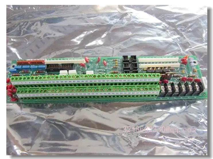
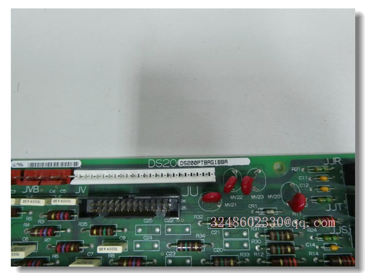
GE DS200PTBAG1B — Speedtronic Mark V RST Analog I/O Board for Gas Turbine Control
Meta Description
GE DS200PTBAG1B analog I/O board for Speedtronic Mark V gas turbine control systems. Scales and conditions LVDT, 4–20 mA, thermocouple, vibration, servo and generator/line signals in R1/R2/R3 I/O cores. Verify full suffix and connector layout before replacement.
Product Core Overview
The DS200PTBAG1B is a GE Speedtronic Mark V series analog I/O board used in gas turbine control systems. It is classified as an RST analog I/O board and works with terminal boards installed in I/O cores R1, R2 and R3, commonly referenced as the TCQA analog I/O/terminal assembly.
The board scales and conditions multiple analog signals read from turbine field devices, including LVDT position inputs, servo valve outputs, thermocouple inputs, 4–20 mA inputs/outputs, vibration inputs, relay driver outputs, pulse inputs, voltage inputs, and generator/line signals. Conditioned signals can be transferred to the STCA board through the 3PL connector, while generator and line signals are exchanged with the TCQC board via the JE connector.
DS200PTBAG1B is a legacy Mark V component. It is typically available as surplus, refurbished or tested used stock rather than as a current GE production item.
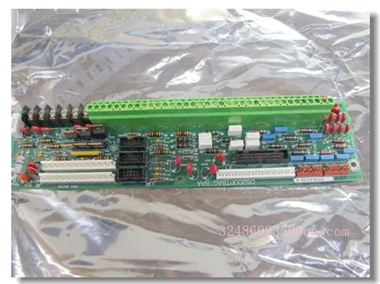
DS200PTBAG1B
Key Technical Specifications
Connector functions are based on the DS200PTBAG1B / TCQA family description; exact pinout and usage must be confirmed against the installed board label and system wiring drawings.
Quality Control Procedures
- Part number confirmation: Verify DS200PTBAG1B, revision code, serial number and board ID.
- Visual inspection: Check PCB condition, connectors, jumpers, fuses, LEDs and terminal blocks.
- Connector verification: Inspect 2PL, 3PL, JE, JB, JF, JG and JD connectors for damage or bent pins.
- Power-up test: Confirm LED indicators and board initialization under safe test conditions.
- Signal validation: Check 4–20 mA scaling, LVDT conditioning, thermocouple inputs and vibration/pulse channels.
- Bus communication check: Verify 3PL data transfer to STCA/TCQA/TCQE and JE exchange with TCQC.
- Documentation: Record revision, jumper settings, test results and replacement history.
Related GE Mark V Models
- DS200PTBAG1A — Mark V protective core terminal board / PTBA-related assembly
- DS200PTBAG1ABA — Mark V RST analog I/O board variant
- DS200TCPDG1B — Mark V I/O / terminal board family
- DS200TCPDG2B — Mark V RST analog I/O board
- DS200CTBAG1A — Mark V turbine control terminal board
- DS200SDCCG4AFD — Mark V turbine control system board
Frequently Asked Questions
What is the DS200PTBAG1B?
It is a GE Speedtronic Mark V RST analog I/O board used to scale and condition analog signals in gas turbine control cores.
It is a GE Speedtronic Mark V RST analog I/O board used to scale and condition analog signals in gas turbine control cores.
Which signals does it handle?
Typical signals include LVDT inputs, servo valve outputs, thermocouple inputs, 4–20 mA I/O, vibration inputs, pulse inputs, relay driver outputs, and generator/line signals.
Typical signals include LVDT inputs, servo valve outputs, thermocouple inputs, 4–20 mA I/O, vibration inputs, pulse inputs, relay driver outputs, and generator/line signals.
Can DS200PTBAG1B replace DS200PTBAG1A directly?
Not automatically. DS200PTBAG1A is described as a protective core terminal board/PTBA-related assembly, while DS200PTBAG1B is an RST analog I/O board. They should not be swapped without engineering confirmation.
Not automatically. DS200PTBAG1A is described as a protective core terminal board/PTBA-related assembly, while DS200PTBAG1B is an RST analog I/O board. They should not be swapped without engineering confirmation.
Is this board still produced by GE?
Most Mark V boards are legacy products. DS200PTBAG1B is commonly supplied as surplus, refurbished or tested used stock.
Most Mark V boards are legacy products. DS200PTBAG1B is commonly supplied as surplus, refurbished or tested used stock.
How is it configured?
Configuration is typically set by hardware jumpers, including J1/J2 for mA output circuit, J5/J6 for 20 mA or 200 mA range, J7 for RS232 card testing, and J8 for oscillator start.
Configuration is typically set by hardware jumpers, including J1/J2 for mA output circuit, J5/J6 for 20 mA or 200 mA range, J7 for RS232 card testing, and J8 for oscillator start.
Installation and Configuration Guide
- Confirm identity: Read the full part number, revision and serial number from the original board label.
- Isolate power: De-energize the Mark V control cabinet and follow lockout/tagout procedures.
- Record existing setup: Photograph jumper positions, connector IDs, ribbon cables and terminal wiring.
- Label wiring: Mark all signal wires and connectors before removal to avoid miswiring.
- Replace the board: Install the DS200PTBAG1B into the correct I/O core slot and secure mounting hardware.
- Restore connectors: Reconnect 2PL, 3PL, JE, JB, JF, JG and other connectors exactly as documented.
- Check jumpers: Set J1, J2, J5, J6, J7 and J8 only after confirming the required configuration.
- Power-up and test: Restore power, verify LEDs, validate analog signal conditioning, and confirm communication with STCA/TCQA/TCQE and TCQC under supervised testing.