

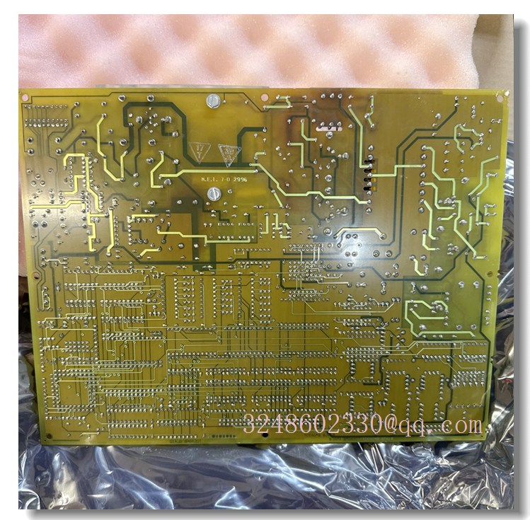
GE DS200TCEAG1B — Speedtronic Mark V Emergency Overspeed (TCEA) Protection Board
Meta Description
GE DS200TCEAG1B TCEA board for Speedtronic Mark V turbine control systems. Provides emergency overspeed protection, flame detection trip and auto-synchronizing functions in the P-core safety layer. Confirm full suffix before replacement.
Product Core Overview
The DS200TCEAG1B is a GE Speedtronic Mark V Emergency Overspeed Board, commonly abbreviated as TCEA. It belongs to the P-core protection layer of the Mark V turbine control system and is used for gas turbine, steam turbine and large rotating equipment protection.
The board monitors turbine shaft speed and flame detection signals, and initiates emergency trip actions when unsafe conditions are detected. It also supports auto-synchronizing functions before generator grid connection. DS200TCEAG1B is a “B” revision of the DS200TCEAG1 family and is typically supplied with an Intel 80196 microprocessor, multiple EPROM/PROM modules, bayonet-style connectors and configurable hardware jumpers.
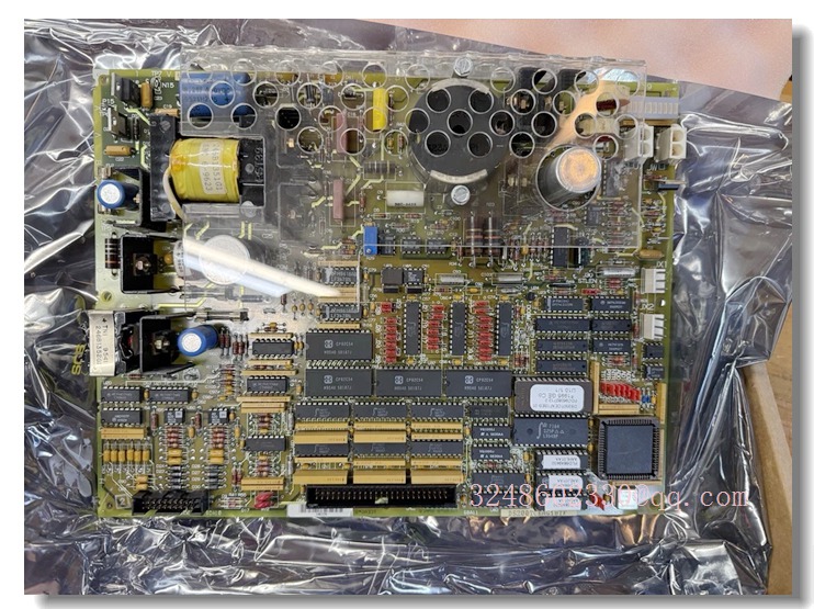
DS200TCEAG1BTF
Key Technical Specifications
Exact trip thresholds, connector pinouts and jumper maps must be confirmed from the installed board label and OEM documentation.
Quality Control Procedures
- Full part number verification: Confirm DS200TCEAG1B, revision suffix and serial number.
- Visual inspection: Check PCB coating, connectors, fuses, jumpers, EPROMs and mounting hardware.
- Connector inspection: Verify bayonet connectors, J7, JK, JL, JW, JX1 and JX2 for damage or bent pins.
- Power-up test: Confirm LED indicators and board initialization under safe conditions.
- Speed input check: Validate magnetic pickup or speed sensor signal conditioning.
- Trip logic verification: Test overspeed and flame detection trip outputs with supervised simulation.
- IONET communication check: Verify JX1/JX2 daisy-chain communication with STCA/TCEB boards.
- Documentation traceability: Record revision, jumper settings, EPROM codes and test results.
Related GE Mark V Models
- DS200TCEAG1ACB — Mark V emergency overspeed/TCEA board variant
- DS200TCEAG1BTF — TCEA emergency overspeed board with full suffix
- DS200TCEAG1BNE — TCEA overspeed protection board variant
- DS200TCEAG1BSF — Mark V protection/I/O board variant
- DS200TCTG1B — Mark V turbine trip board, receives trip signals from TCEA
- DS200TCPSG1A — Mark V power supply board for turbine control cores
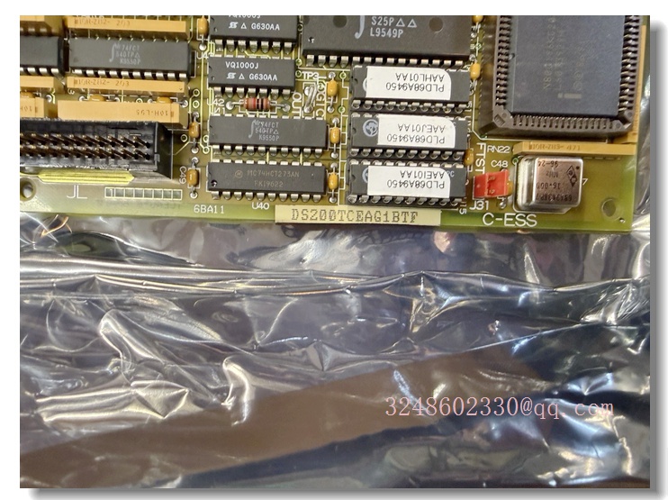
DS200TCEAG1BTF
Frequently Asked Questions
What is the DS200TCEAG1B?
It is a GE Mark V Emergency Overspeed Board, also called the TCEA board. It provides hard-wired overspeed and flame detection protection for turbine systems.
It is a GE Mark V Emergency Overspeed Board, also called the TCEA board. It provides hard-wired overspeed and flame detection protection for turbine systems.
Is DS200TCEAG1B the same as DS200TCEAG1?
Not exactly. DS200TCEAG1B is a “B” revision of the DS200TCEAG1 family. Revisions may differ in firmware, jumpers or connector configuration, so they should not be swapped without engineering approval.
Not exactly. DS200TCEAG1B is a “B” revision of the DS200TCEAG1 family. Revisions may differ in firmware, jumpers or connector configuration, so they should not be swapped without engineering approval.
Can it be replaced directly in the field?
Only after confirming the full suffix, EPROM content, jumper settings and IONET address. The board is part of the safety trip path, so incorrect replacement may affect turbine protection.
Only after confirming the full suffix, EPROM content, jumper settings and IONET address. The board is part of the safety trip path, so incorrect replacement may affect turbine protection.
Is this board still produced by GE?
Most Mark V boards are legacy products. DS200TCEAG1B is commonly available as new surplus, refurbished or tested used stock.
Most Mark V boards are legacy products. DS200TCEAG1B is commonly available as new surplus, refurbished or tested used stock.
Where is it installed?
It is installed in the Mark V P-core rack and communicates with TCEB, TCTG and other control boards through dedicated connectors and IONET links.
It is installed in the Mark V P-core rack and communicates with TCEB, TCTG and other control boards through dedicated connectors and IONET links.
Installation and Configuration Guide
- Confirm the full suffix: Read DS200TCEAG1B plus any additional suffix from the original board label.
- Isolate power: De-energize the Mark V control cabinet and follow lockout/tagout procedures.
- Record configuration: Photograph jumper positions, EPROM locations, connector IDs and LED status.
- Handle with ESD protection: Use anti-static wrist straps when handling the PCB and EPROM modules.
- Transfer EPROMs if required: If the replacement board does not include programmed EPROMs, transfer them from the original board exactly as documented.
- Set jumpers carefully: Configure IONET address, termination and overspeed trip jumpers only after confirming the plant-specific settings.
- Reconnect wiring: Reinstall J7, JK, JL, JW, JX1 and JX2 connectors and verify bayonet locking.
- Power-up and test: Restore power, check LEDs, validate speed inputs, and confirm trip logic and IONET communication under supervised testing.