

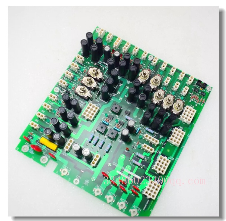
GE Speedtronic Mark V I/O Board DS200TCPDG1B — Turbine Control System Terminal/Analog I/O Board
Meta Description
GE DS200TCPDG1B series board for Speedtronic Mark V gas and steam turbine control systems. Used for analog/terminal I/O, signal conditioning and rack-mounted turbine control applications. Confirm full suffix and board revision before replacement.
Product Overview
The DS200TCPDG1B family belongs to GE’s Speedtronic Mark V turbine control platform. These boards are used in gas and steam turbine control systems to support analog signal conditioning, terminal interfacing and I/O communication between field devices and the main control processors.
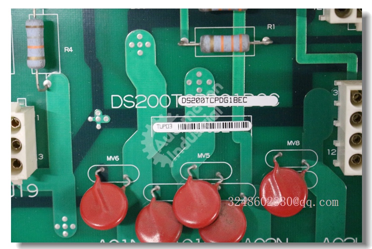
In many listings, DS200TCPDG1B appears with additional suffixes such as DS200TCPDG1BDC, DS200TCPDG1BBA or DS200TCPDG1BCC. The suffix usually identifies the exact board revision, connector layout and application variant. Some sources describe the family as an analog/terminal I/O board for R/S/T or core rack arrangements, while others list similar part numbers as digital I/O or bus-related modules. Therefore, the exact function must be confirmed from the physical label.
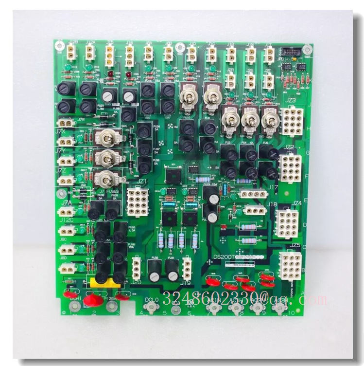
DS200TCPDG1B
Key Technical Specifications
For reference, closely related DS200TCPDG1B variants have been described as analog I/O or terminal boards used in Mark V R/S/T core racks, handling signals such as LVDT inputs, servo valve outputs, 4–20 mA signals, thermocouple inputs, vibration inputs and generator/line signals. However, these details should not be assumed for DS200TCPDG1B without verifying the full suffix.
Quality Control Procedures
- Part number verification: Confirm full model suffix, revision code and board ID.
- Visual inspection: Check PCB, connectors, fuses, LEDs, terminals and mounting hardware.
- Connector check: Inspect J-type connectors, ribbon cables and backplane contacts.
- Power-up test: Verify LED indicators and board initialization under safe conditions.
- I/O verification: Test analog/digital channels against the original system configuration.
- Documentation traceability: Retain test records, revision data and replacement history.
Related GE Mark V Models
- DS200TCPDG1BDC — Mark V analog/terminal I/O board variant
- DS200TCPDG1BBA — Mark V digital I/O module variant
- DS200TCPDG1BCC — Mark V PLC/control system board variant
- DS200TCPDG1BEC — Mark V digital output/fuse board variant
- DS200TCPDG2B — Mark V RST analog I/O board
- DS200CTBAG1A — Mark V terminal board for turbine control
Frequently Asked Questions
What is DS200TCPDG1B?
It is a GE Speedtronic Mark V series board used in turbine control systems, typically as an I/O or terminal board.
It is a GE Speedtronic Mark V series board used in turbine control systems, typically as an I/O or terminal board.
Can DS200TCPDG1B be replaced directly?
Only if the full suffix, revision and connector layout match. DS200TCPDG1BDC, DS200TCPDG1BBA and DS200TCPDG1BCC may not be interchangeable.
Only if the full suffix, revision and connector layout match. DS200TCPDG1BDC, DS200TCPDG1BBA and DS200TCPDG1BCC may not be interchangeable.
Is this board still produced by GE?
Most DS200 Mark V boards are legacy products and are commonly supplied as new surplus, refurbished or tested used units.
Most DS200 Mark V boards are legacy products and are commonly supplied as new surplus, refurbished or tested used units.
Where is it used?
Typically in gas turbine, steam turbine and power generation control cabinets using the Mark V platform.
Typically in gas turbine, steam turbine and power generation control cabinets using the Mark V platform.
Installation and Configuration Guide
- Identify the exact suffix: Read the full part number from the original board label before removal.
- Isolate power: De-energize the control cabinet and follow lockout/tagout procedures.
- Record configuration: Photograph connector positions, jumper settings and LED status.
- Handle with ESD protection: Use an anti-static wrist strap when handling PCBs.
- Replace the board: Insert the replacement into the correct rack slot and secure mounting hardware.
- Reconnect wiring: Verify all connectors, ribbon cables and terminal blocks match the original layout.
- Power-up check: Restore power and observe LED indicators for normal board initialization.
- Functional test: Validate I/O signals, turbine control responses and alarm/trip functions under supervision.